Electrical was a big enough task to separate the documentation into two parts - the first part being the branch circuit wiring on the inside (“post panel”) and the second part being the inverter, disconnects, and larger wires inside the electrical closet (“pre panel”).
At least for the branch circuits, a work-backwards approach from the end points was needed, so I mapped out all the fixtures, switches, and appliances in order to group devices into circuits. In a full-size house, this would usually be easy as the circuits are grouped by rooms, but I don’t really have rooms so it was more of an issue of optimizing wiring length and making sure wire ran efficiently between boxes. Below is a diagram of all the endpoints and switches that required wiring, with the circuit groupings shown. The right side of the diagram is a layout of the electrical closet which will be covered in part 2.
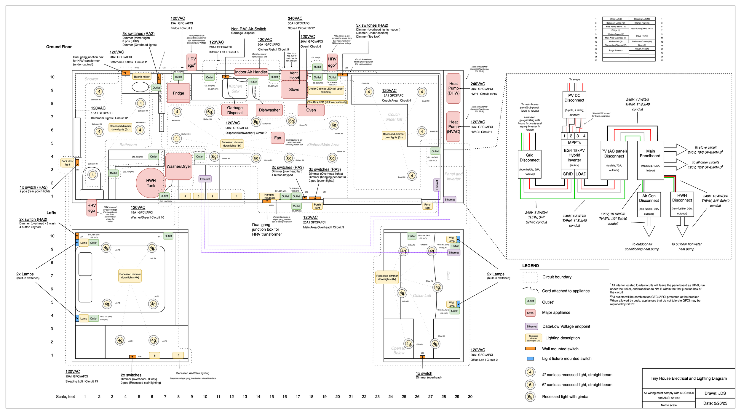
One major decision affecting the branch wiring was routing the “home runs” under the trailer from the panel. I did this because I didn’t want to blast huge holes in the framing to fit a bunch of wires through, and the underside of the trailer is relatively flat and open which would make routing easier. Since this area is damp/exterior, Romex (NM) wire isn’t allowed so I decided on UF to complete the majority of the horizontal distance, before entering the house through the bottom and transitioning to NM inside the first junction box.
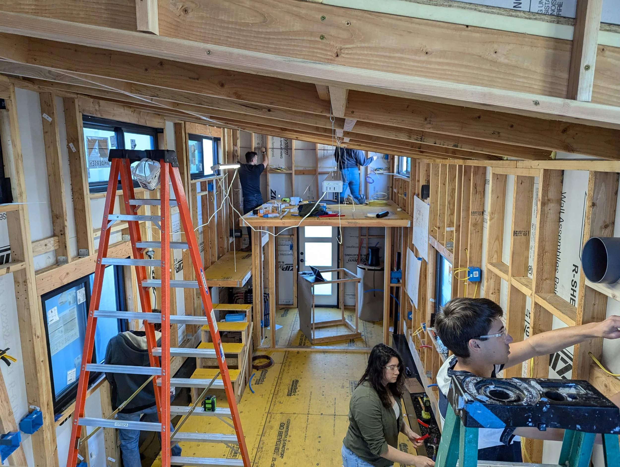
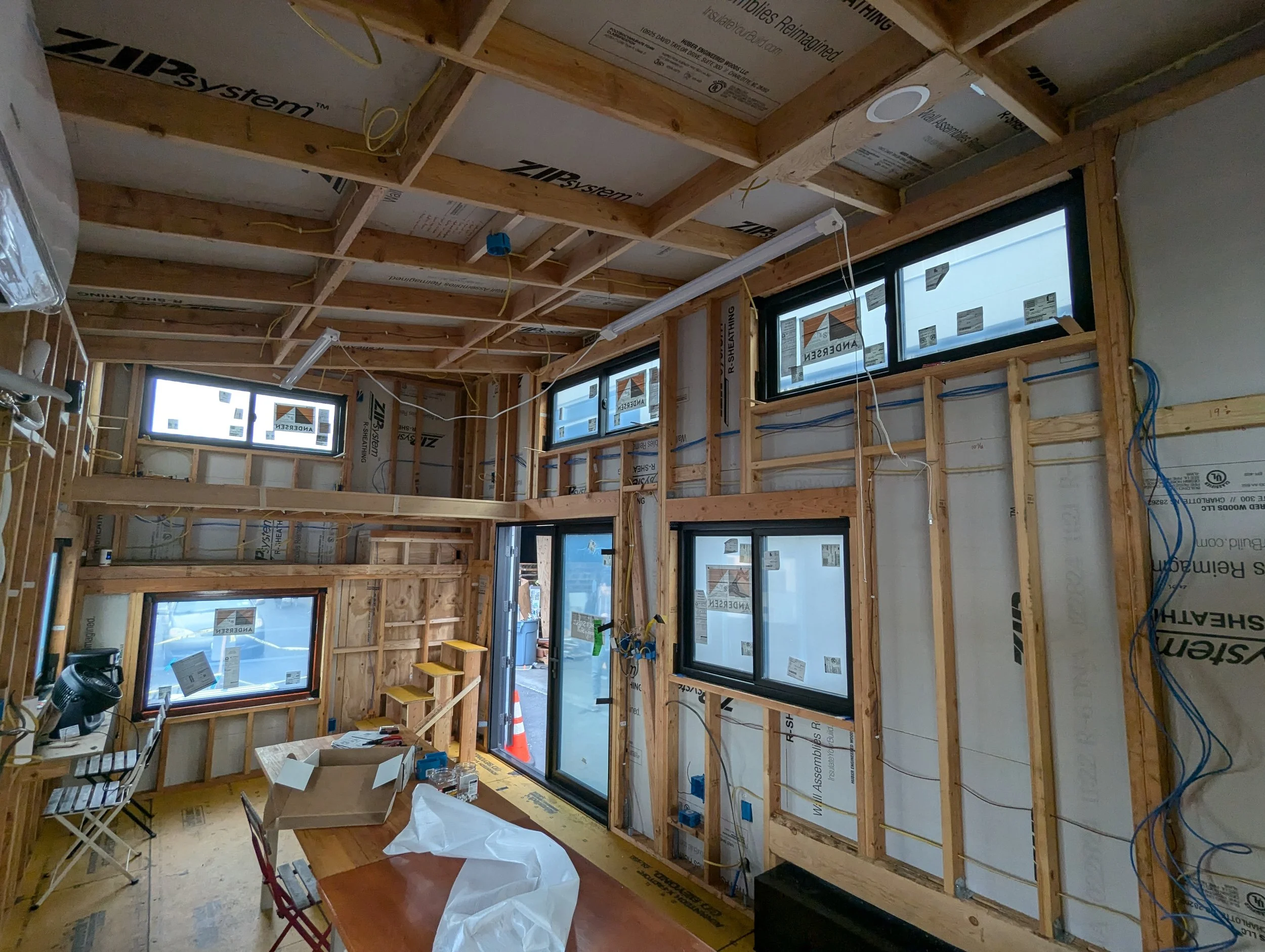
I had a lot of help the first day of wiring with some friends in town. The entire house is 12AWG as I just never wanted to worry about 20 vs 15A circuits. Most circuits are 12-2 and I think I went through about 750 feet of it - this is partly because the number of circuits I have is way overkill for a tiny house! The stove is 10-3 and there is one run of 12-3 in the bedroom for a multi-location switch. All boxes are PVC. I also ran 4 lengths of CAT5 ethernet through the wall to connect the router/modem area to the office and inverter.
I highly recommend getting a 90 degree drill for drilling through holes in studs. I positioned my wire holes dead center and used a 1/2” and sometimes 5/8” bit to avoid needing nail plates.
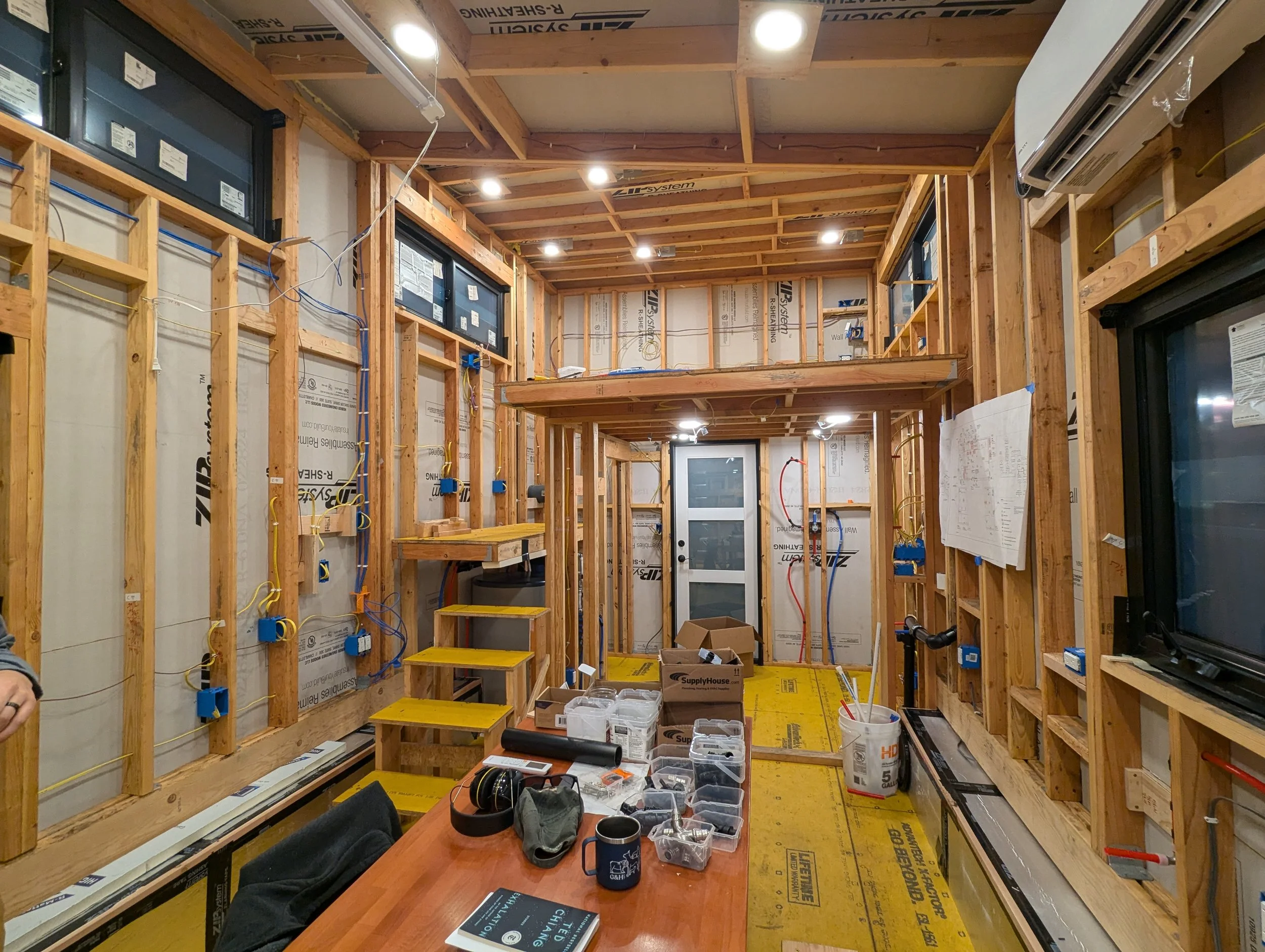
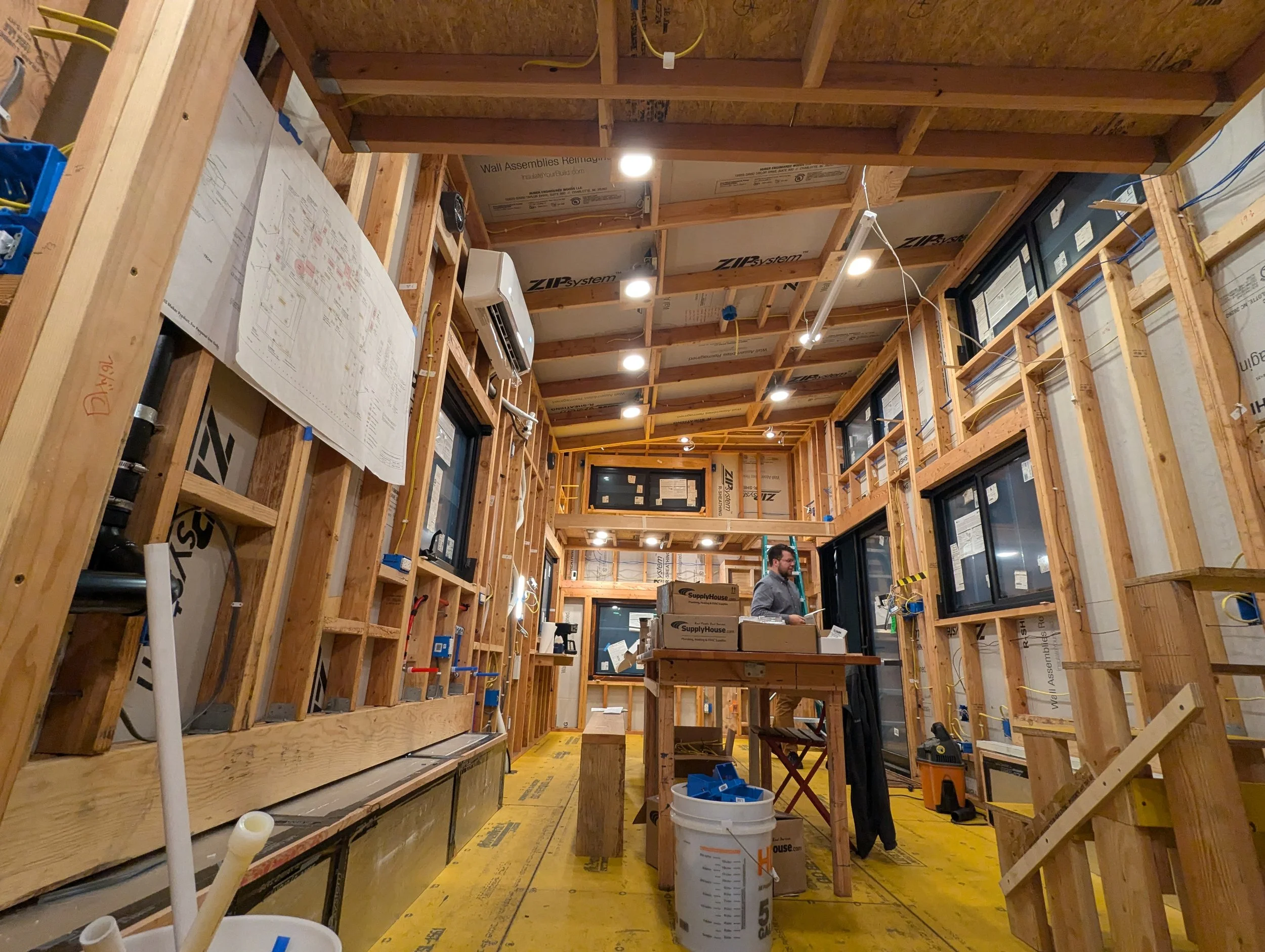
I also leaned toward overdoing on lighting. Every “ceiling” has LED can lights, those of which that are on sloped ceilings are also gimbaled to be angled straight down. Most of these can lights have a controller in which the wiring terminates, and then a low voltage wire to the actual light. This is convenient as I could install the box, and then leave the light off while putting up the interior wall panels and run the low voltage cable through the hole, paint, etc, and then reinstall the light. All lights are built-ins except for select fixtures:
For these fixtures, the wiring terminated in the box for later installation of the fixture. I also planned on under-cabinet and toe-kick lighting. Attached below are the quotes for all the can lights and strip lights.
City Lights Order 1.PDF
City Lights Order 2.PDF
All outlets were standard Home Depot offerings - even the USB ones.
To control all the lights I will be the first to admit I balled out - I went with the RadioRa3 system from Lutron which cost an arm and a leg but after having lived with it for 6+ months it is great and was worth it. I really did not like the feel of the Caseta switches, and wanted more advanced functionality than Caseta offered like the Sunnata keypads. Unfortunately that meant jumping all the way up to RadioRa3, as RadioRa2 seemed so close to 3 but with different training and slightly more limitation. To download the RadioRa3 programming software you have to take an online course through Lutron which took about 4 hours. You are also supposed to prove to the retailer that you have taken the class, but I’m not sure how stringent they are with that - below is the summary of my Lutron order:
Lutron Order.PDF
Once everything was wired up, connecting to the processor and programming the system was very straightforward. I got all my scenes working out of the box in a few hours.
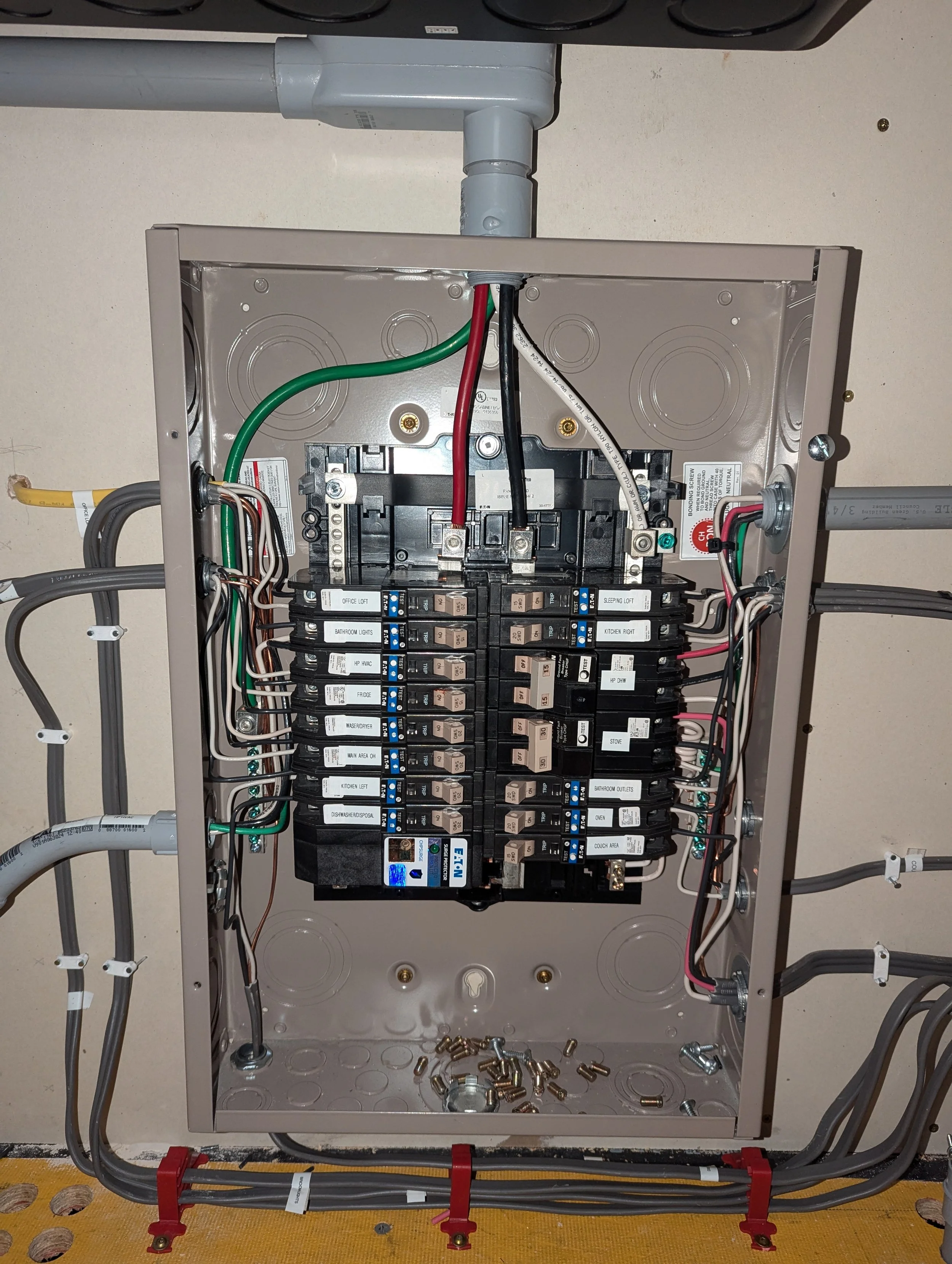
While the panel needed to be wired to show those pictures of the lights on, I’m showing it later on. I went with the Eaton CH series combo GFCI/AFCI breakers for all circuits except for the strove and hot water heater circuits - these are just GFCI because they are 240V. These breakers are expensive by the peace of mind of having AFCI was worth it. They are also all PON (Plug-on-Neutral) so no pigtails were needed for the GFCI functionality.
I also installed an Eaton surge protector directly to the panel.